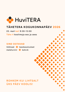
Kogukonnapäev 2026
Tule saa osa põnevast kogukonnapäevast! Toimuvad erinevad töötoad, esinemised, maleturniir, taaskasutuslaat ning avatud on HuviTERA kohvik! Üritus on TASUTA! Kohvikus ja taaskasutuslaadal arveldame sularahas. Kogukonnapäev
Tule saa osa põnevast kogukonnapäevast! Toimuvad erinevad töötoad, esinemised, maleturniir, taaskasutuslaat ning avatud on HuviTERA kohvik! Üritus on TASUTA! Kohvikus ja taaskasutuslaadal arveldame sularahas. Kogukonnapäev

Tuletame meelde, et järgmisel nädalal, 23.veebruar – 1.märts on koolivaheaeg ning HuviTERA ringitunde ei toimu!
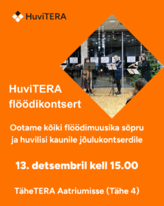
Tule veeda rahulik pärastlõuna õrnalt heliseva flöödimuusika seltsis! 🎶✨HuviTERA flöödiõpilased koos õpetajaga ootavad huvilisi flöödikontserdile 13. detsembril kell 15.00 TäheTERA Aatriumisse.